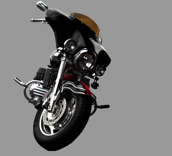
Valkyrie owners here are the Instructions for mounting the XF6 tachometer, speedometer and headlight relocation kit which is a precursor to mounting the quadizilla fairing manufactured by Hoppe Industries to your motorcycle.
Parts included in mounting kit:
Qty Description
1 Headlight Bracket
2 8mm
2 8mm Washers
2 8mm Nuts
3 6mm Bolts
3 6mm Washers
3 6mm Nuts
2 Tachometer/speedometer Mounting Bracket
2 Handlebar Mounting Clamp Assemblies
2 8mm Bolts
2 8mm Acorn Nuts
4 6mm Bolts
4 6mm Acorn Nuts
1 *Custom Length Speedometer Cable
*Speedometer cable works with stock handlebars and risers. If you are using custom risers that have more than two inches of rise or pull back there is the chance you will need to have a longer speedometer cable than is provided.
1. Remove windshield
2. Remove Headlight bezel
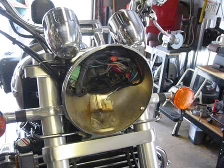
3. locate color coded tach and speedo wires and disconnect inside the headlight bucket.
4. Pull the disconnected wires out the rear of the opening of the headlight bucket. Note; it is not necessary to disassemble either the tach or speedometer housing, or splice extra length of wire in to the wiring looms. There is sufficient length of wire in the headlight bucket to accomplish the relocation.
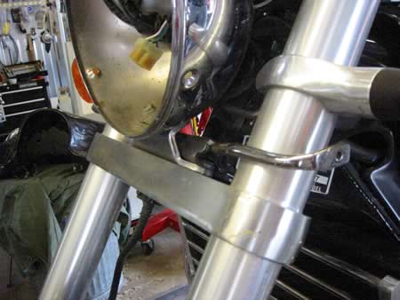
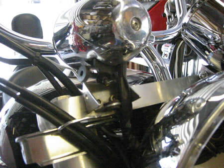
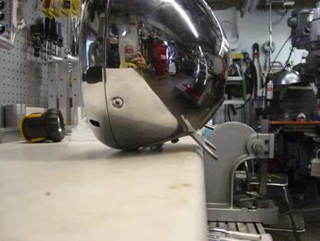
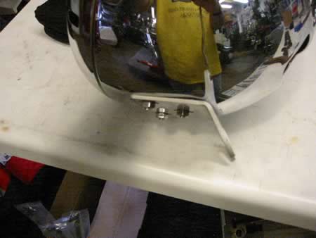
5. Remove the three bolts in side the headlight bucket that hold it to the stock bracket. Then remove the two stock bolts that hold the stock bracket to the bottom triple tree.
Using the new slotted bracket and 8mm caphead bolts, attach new bracket to the bottom triple tree, initially tighten these two bolts lightly as you will be readjusting this bracket later. Now using the three 6 mm caphead bolts, washers and nuts attach the headlight bucket to the slotted headlight bracket. Note; the caphead side of the bolts should be on the inside of the headlight bucket and the nuts should be on the outside against the bracket. Tighten these finger tight also, you will be readjusting and tightening later.
6. Disconnect stock length speedometer cable, make special note of how this cable is routed. Note; use Honda maintenance manual for disassembly reference.
7. Remove the tach and speedometer from the the upper triple clamp. Take special note of how this is done as you will have to reverse the procedure when installing these parts on your new mounting brackets. You will first remove the acorn nut on the bottom of the stock mounting pad then remove the nut and bolt that holds the tach and speedo into the bracket. You can now gently rock and pivot the tach and speedo out of there stock mounting bracket. You now have access to the two cap head screws that secure these brackets to the triple tree. Remove these 6mm caphead bolts. Note; experience has taught us that you may need to use a handheld impact to break these loose.
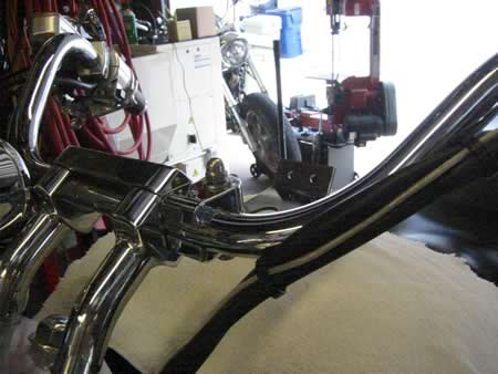
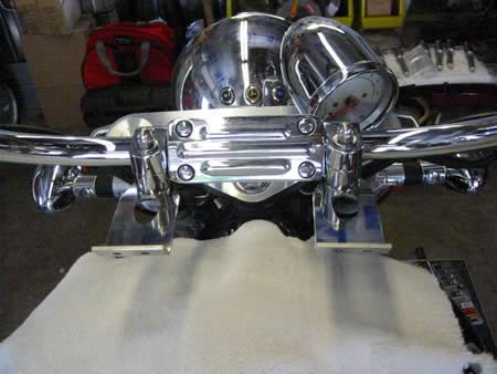
8. Mount the new tach and speedo relocation brackets on your handlebars on either side of the risers. They should be mounted initially so that they are parrelel to the ground and the clamp bolt snugged up just enough to keep them from slipping as you continue installation.
9. Using the two 6mm caphead bolts provided with the new tach speedo brackets. Reassemble the tach and speedo bracket assemblies, the new 6mm bolts should be protruding out the back of the stock Honda mounting brackets. Now taking this assembly you will feed the wires you disconnected earlier down thru the teardrop opening in the new brackets, using a slight rearward angle you can rock and pivot the assembly into place on the handlebar relocation mounts. Note, it may take a little patience to get the bolts to go thru the holes, under know circumstances should this be a forced fit. At this point of assembly its helpful to use an allen wrench to help guide the bolts into the bracket, its also helpful to have a second set of hands to assist you.
Once this is accomplished lightly tighten the acorn nuts provided.
10. Route the speedo/tach wires back to the headlight bucket. Do this in such a way that they don’t bind or are pinched, this is a good place to use some little black wire ties to keep things tidy. Reconnect all the your color coded wires and check the operation of all the indicator lights in the speedo and tach for proper operation.
Note; if you are installing after market turn signals and need to do any splicing into the existing turn signal wires that are located in the headlight bucket, this would be the time to accomplish that task.
Now you are ready to install the fairing. Refer to the Hoppe installation instructions provided with your fairing.
In most cases this will involve removing the gas tank in order to route the wiring harness.
There are a couple of important tips I would like to pass on to the installer.
When you initially tighten the worm clamps of the inner fairing shell to the forks, you should tighten these just enough to keep the inner fairing from slipping down while you are doing subsequent steps in the installation. If tighten the clamps all the way at this point you will probably distort the alignment between the inner and outer shell attachment bolts. The final tightening of the clamps will be one the last steps in the installation.
It cannot be over emphasized enough that inorder to get proper fitment of this fairing on a Valkyrie that the fairing be mounted as high on the upper triple tree as the fairing will allow this allows proper headlight clearance and adjustment later.
Once you have the outer shell and windshield bolted to the inner fairing shell, check to make sure the fairing did not slip down from the upper triple tree. When your sure that it is in the proper position , finish tightening the worm gear clamps to the forks.
Adjust the headlight fitment. Finish tightening the two 8mm bolts of the slotted headlight bracket to the lower triple tree.
When the headlight is adjusted vertically then finish tightening the three 6mm caphead bolts in the headlight bucket and install the headlight bezel and screws. Check the headlight fitment to the fairing. You should clearance between the headlight and fairing. Readjust as necessary to achieve this clearance.
Always double check that all your bolts, nuts and clamps are secure. In addition you should check and adjust as necessary the aiming of the headlight.
If you have any questions call Daryl at 414-517-9546 or Contact here.